FdF
This project is about creating a simple wireframe model representation of a 3D landscape by linking various points (x, y, z). Create a 3D model from 2D map of numbers.
C
Makefile
MLX42 Library
realization
1.Input Validation
In this stage, the program checks that exactly one argument (a text file with the .fdf extension) has been passed. It also verifies that the file can be opened and read.
2.Map Parsing
The program reads the file using the get_next_line function and stores the content in an array of strings. It also counts the number of rows and columns in the map.
3.Map Conversion
Here, the map is converted into a struct containing height (z) values. The array of strings is transformed into a point struct, storing the numeric values. If the map includes colors (separated by commas), the program converts these into RGBA format. If no color is specified, default colors are applied based on the z value. The memory used in the previous step is then freed.
4.Setting Coordinates
This step fills the 'point' struct with corresponding x and y coordinates.
5.Scaling Point Values
In this phase, the points are scaled according to the total number of points in the map. This controls the spacing between points.
6.Rotating Points
After scaling, matrix rotation formulas are applied to change the model's angle along the:
x-axis
y-axis
z-axis
Important! The original angle values are stored before rotation. Zooming, height scaling and rotation examples are provided below:

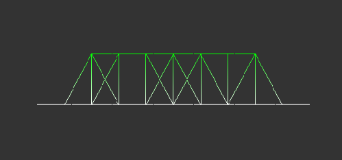
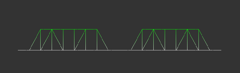
7.2D Projection Conversion
The program converts the 3D coordinates into either isometric or orthographic projections. Examples of different projections are shown below:

8.Centering and Moving Points
Next, the model is moved to avoid image cropping by aligning it with the left and top edges of the screen. It is also centered based on the window size. User-controlled movement is added in this phase. Moving example is shown below:
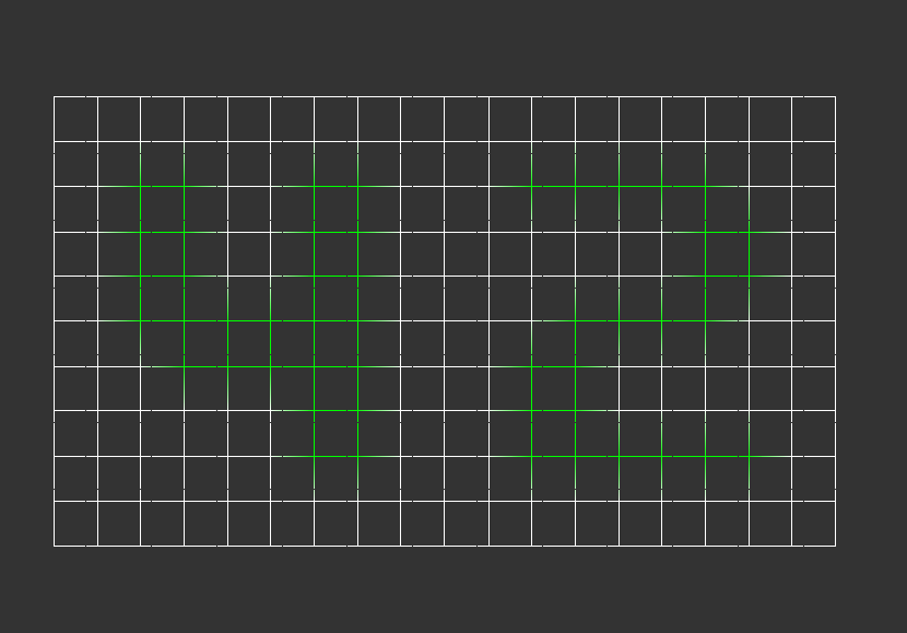
9.Line Drawing
This section uses the DDA (Digital Differential Analyzer) algorithm to draw lines. First, horizontal lines are drawn, followed by vertical lines.
10. Setting up Keyboard and Mouse Controls
Here, keys and mouse controls are configured to change between isometric and orthographic projections, move the model, rotate it, zoom, and adjust the height scaling. After closing the program (by pressing ESC or clicking the Close button), all allocated memory is cleaned up.
See on GitHub